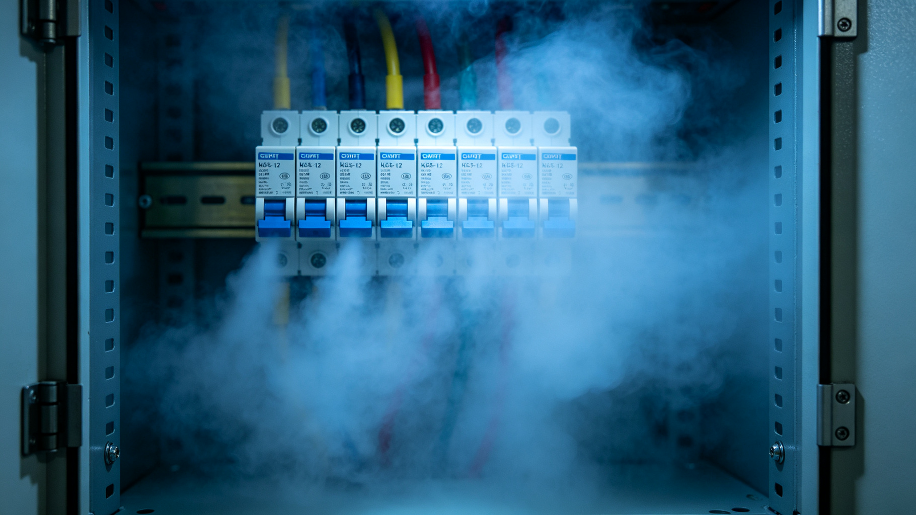
Technical guide on agent dispersion for electrical fire protection
A suppression agent that never reaches the ignition source is merely expensive gas. Diffusion dynamics determine whether a discharge protects the entire enclosure or leaves dangerous dead zones. Understanding how molecular weight, discharge pressure, and nozzle placement interact is the first step toward designing a system that actually works when it matters.
Enclosed electrical compartments such as switchgear cubicles, UPS cabinets, drive panels, and junction boxes present a difficult fire-protection problem: ignition sources are close to combustible insulation, volumes are congested, and a growing fire may be hidden behind metal covers before manual response is possible. The QuellPatch product line from FIREQUELL uses microencapsulated FK-5-1-12 clean agent and passive thermal activation to address this hazard at the compartment scale. Patches are rated for activation at 80°C, 140°C, or 180°C and have a 5-year service life, allowing them to be installed near likely ignition zones without piping, cylinders, or electronic controls.
Because these devices do not discharge through high-pressure nozzles, their performance depends strongly on clean agent release behavior, local agent dispersion, and subsequent enclosure mixing. This article examines how FK-5-1-12 leaves a thermally activated patch, how it moves through congested electrical compartments, and how a practical diffusion model can be used to estimate concentration development. The focus is engineering behavior, not generic clean-agent properties.
A QuellPatch contains many FK-5-1-12-filled microcapsules bonded to a flexible substrate. When the patch surface reaches its rated temperature, the polymer shells lose tensile strength while the vapor pressure of the encapsulated agent rises. Rupture does not necessarily occur as a single event. In representative bench-scale heating tests, capsules exposed to temperatures moderately above their rating ruptured over tens of seconds, while exposure to temperatures well above the rating produced a shorter, more concentrated release. For example, an 80°C patch on a surface held near 95°C may release most of its mass over approximately 30–90 s, whereas a 180°C patch exposed to a 250°C surface may release most of its mass in roughly 5–20 s.
This distributed source term matters. A fast release can produce a high local concentration near the patch, while a slower release may allow mixing and leakage to reduce peak concentration. The 80°C variant is commonly suited to enclosed electronics or cable compartments where early response is useful and normal ambient temperatures remain low. The 140°C variant is often selected for general switchgear or busbar compartments where surface heating can occur during normal operation. The 180°C variant is appropriate for higher-ambient locations or compartments near heat-producing equipment where a higher activation threshold reduces the likelihood of unintended response.
FK-5-1-12 has a boiling point near 49.2°C, so at all three activation temperatures the released agent is above its boiling point at atmospheric pressure. A portion of the discharged mass flashes directly to vapor, while some may leave the patch as fine droplets that vaporize within a short distance. The discharge velocity is low compared with a nozzle-based total-flooding system; engineering estimates for patch-face vapor velocities are typically on the order of 0.5–2 m/s, depending on temperature and capsule loading.
The result is an area source rather than a momentum jet. Near the patch, local volume concentrations can exceed the common FK-5-1-12 design range of roughly 4.5–6% for electrical and Class B hazards. Farther from the patch, concentration depends on gravity spread, advection, and diffusion rather than on nozzle throw. This distinction is central to modeling QuellPatch performance in small enclosures.
FK-5-1-12 vapor has a molecular weight of approximately 316 g/mol, compared with about 29 g/mol for air. Even at elevated release temperatures, the vapor remains denser than the surrounding cabinet air. At 80°C, its ideal-gas density is roughly nine times that of 20°C air; at 180°C, it is still roughly seven times as dense. The released agent therefore tends to spread downward and outward along horizontal surfaces, forming a dense layer before global mixing occurs.
Electrical compartments modify this behavior. Cable bundles, circuit breakers, busbars, mounting plates, and partition plates block vertical descent and create lateral flow channels. In representative compartments with volumes of 0.2–1.0 m³, dense-layer formation near the bottom or behind equipment can begin within 5–15 s, while approximate global mixing may require 20–90 s. A fire plume or hot surface can also lift some agent upward, so the actual flow field is a combination of gravity current, thermal plume, and obstacle wake.
Many electrical compartments contain forced-air cooling or develop natural convection currents from hot busbars and transformers. These flows can accelerate enclosure mixing and reduce stratification, but they can also carry agent toward leakage paths. Door gaskets, cable glands, ventilation openings, and panel seams allow mass exchange with the surrounding room.
Because FK-5-1-12 vapor is dense, low-level openings are particularly important. A sealed cabinet may retain an effective concentration for several minutes, while a cabinet with bottom cable openings or unsealed ventilation may lose agent more rapidly. For design purposes, leakage should be treated as part of the mixing problem rather than as a separate afterthought.
A useful diffusion model for QuellPatch deployments solves an advection-diffusion equation for agent concentration:
∂c/∂t + ∇·(u c) = ∇·(Deff ∇c) + S(x,t)
where c is agent concentration, u is the local air velocity, Deff is an effective dispersion coefficient, and S(x,t) is the patch source term. Molecular diffusion of FK-5-1-12 in air is relatively slow, with coefficients often estimated near 0.05–0.10 cm²/s. In ventilated or thermally active compartments, turbulent and wake-driven dispersion can increase the effective coefficient to tens or hundreds of cm²/s.
The source term S(x,t) should reflect the patch rating and measured thermal exposure. A common approach is to represent capsule rupture as a cumulative lognormal or Arrhenius-influenced distribution in time, with faster release at higher excess temperatures. The model does not require a high-momentum jet submodel because the patch has no nitrogen superpressurization; instead, it should resolve the patch as a low-velocity area source with dense-gas behavior.
For preliminary screening, a well-mixed compartment model can estimate average concentration after a mixing time τmix. In many small electrical compartments, τmix may range from approximately 15–90 s depending on obstruction density and convection. If the required suppression concentration must be reached before τmix, patch placement near the ignition source becomes more important than total compartment mass alone.
For congested or leaky compartments, a zonal model is more appropriate. It can divide the cabinet into upper, lower, and equipment-filled regions and exchange mass between them using flow coefficients. Computational fluid dynamics may be warranted for critical compartments with complex geometry, forced ventilation, or unusual leakage. In all cases, concentration decay after release can be approximated by c(t) = c0 exp(-k t/V), where k is an effective leakage rate and V is compartment volume, with a stratification correction when low-level openings dominate.
Because QuellPatch discharge has low momentum, patches should generally be placed above or immediately adjacent to the components most likely to ignite, such as breaker terminals, busbar joints, contactors, or cable transition points. A practical target is to keep the patch within roughly 0.3–0.6 m of the protected surface when geometry allows, while avoiding direct metal barriers that would block downward vapor spread. Multiple patches may be needed in compartments larger than about 1 m³ or in compartments separated by solid partitions.
Temperature rating should be selected using measured normal and abnormal surface temperatures. The 80°C patch is suitable where ambient and surface temperatures remain well below activation under normal operation. The 140°C patch provides a higher threshold for switchgear compartments with moderate radiant or resistive heating. The 180°C patch is intended for high-ambient or high-operating-temperature locations. An engineering margin should be applied to avoid activation from normal heating while still ensuring response during an incipient fire.
QuellPatch devices have a 5-year service life. Microencapsulation helps isolate the FK-5-1-12 charge from moisture and minor environmental cycling, but the patches should be visually inspected during routine compartment maintenance for damage, dislodgement, or surface degradation. They do not provide a pressure gauge, so replacement at the end of the rated service interval is recommended.
If the compartment layout changes—for example, if cable bundles are added, ventilation is modified, or patches are relocated—the diffusion model should be updated. Agent dispersion is geometry-dependent, and a placement that was acceptable for one configuration may not provide the same mixing behavior after equipment changes.
Clean agent release from QuellPatch devices is governed by thermal microcapsule rupture, low-velocity vapor discharge, dense-gas spreading, and compartment-specific mixing. FK-5-1-12’s high vapor density means that agent initially moves downward and around obstructions, while convection and leakage determine whether effective concentrations persist. A practical diffusion model should represent the patch as a distributed, temperature-dependent source, include an effective dispersion coefficient, and account for leakage and stratification. With appropriate placement, temperature-rating selection, and periodic replacement at the 5-year service interval, QuellPatch can be integrated into an electrical-compartment fire strategy as a passive suppression component.
A: Release timing depends on patch rating and how far surface temperature rises above that rating. Near the activation threshold, capsules may rupture over tens of seconds; at much higher temperatures, release can occur within a few seconds as the polymer capsules respond rapidly to heat.
A: It may not mix evenly at first. Because FK-5-1-12 vapor is denser than air, it initially spreads downward and along surfaces, with cable bundles and equipment creating local zones of higher concentration. Natural convection and leakage gradually distribute the agent, so placement close to the likely ignition point is important.
A: Models typically combine agent mass release, enclosure volume, leakage area, temperature, and air movement to estimate concentration versus time. For total-flood systems, NFPA 2001 sets design and retention requirements; for local passive patches, modeling is best used to check that agent reaches the target component rather than to assume uniform room concentration.
A: Yes, ventilation openings, door gaps, cable penetrations, and cooling louvers can allow agent to escape before it reaches an effective local concentration. In compact, relatively sealed enclosures, released FK-5-1-12 can remain near the protected component longer; in heavily ventilated gear, additional patches or complementary suppression may be needed.
A: Place patches directly above or adjacent to high-risk heat sources such as busbar joints, terminations, circuit breakers, contactors, and cable bundles. Because FK-5-1-12 vapor is denser than air, mounting above the target allows the agent to spread downward across the ignition zone rather than relying on whole-cabinet mixing.
FIREQUELL QuellPatch delivers automatic, maintenance-free clean-agent protection for electrical panels, battery cabinets and control rooms — designed to meet FM Approved, UL Listed, CE and UKCA requirements.
Request a Site Assessment