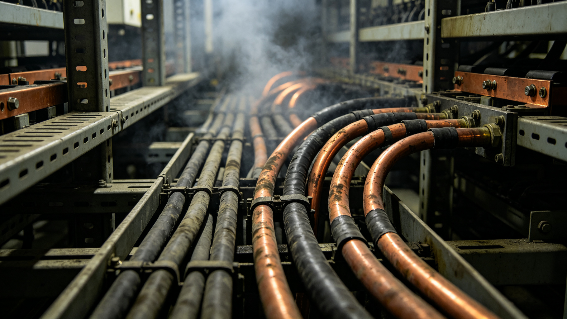
Technical guide on cable fire for electrical fire protection
Cable and busbar failures account for a significant share of electrical fires in industrial and utility installations. Insulation breakdown, loose connections, and overloading create localized hot spots that can smolder for hours before open flame appears. Early detection and targeted suppression inside the enclosure are critical to preventing cascading damage.
Cable and busbar circuits are the arterial infrastructure of commercial, industrial, and utility electrical systems. They are also a persistent fire challenge because the same polymeric materials that provide insulation and mechanical protection can become fuel after a localized electrical fault. A cable fire often begins not in the middle of a healthy cable span, but at a termination, splice, busbar joint, or damaged section where resistive heating, arcing, or tracking develops. Once established, fire can move through cable trays, risers, and busbar enclosures faster than many facility response assumptions allow.
Passive protection has therefore become an important layer in electrical cable risk management. Rather than relying only on detection, manual response, or total-flooding gaseous systems, engineered local devices can intervene at the earliest stage of heating. This article examines the causes and propagation of cable fire and busbar fire events, then explains how the QuellCoat product line uses microencapsulated FK-5-1-12 clean agent for cable tray protection and high-risk busbar locations.
Most electrical cables are rated for defined continuous conductor temperatures, commonly 70°C or 90°C for thermoplastic and cross-linked polyolefin constructions. When those temperatures are exceeded for prolonged periods, insulation undergoes oxidative and thermal aging. As a rough engineering rule, polymer life can be halved for each 8–10°C increase above rated temperature, although the exact factor depends on formulation and environment. Over time, embrittlement, cracking, and reduced dielectric strength create conditions for tracking and arcing.
Terminations are frequent hotspots. A poorly crimped or loose lug can develop contact resistance in the milliohm range. For example, a 0.5 mΩ resistance at 400 A dissipates about 80 W as I²R heat; at 2,000 A, the same resistance dissipates approximately 2 kW. That heat does not disappear into the conductor alone—it conducts into insulation, heat-shrink boots, cable ties, and adjacent cables. Dust, moisture, and chemical contamination can further reduce surface resistance and produce leakage currents that carbonize insulation surfaces.
Arcing faults are more severe than simple overheating. Arc temperatures can exceed several thousand degrees Celsius, producing molten metal, ionized gas, and localized heating well above the 350–500°C range at which common cable insulation materials may ignite. Even a brief arc can ignite nearby polymeric materials if the heat is not removed or suppressed quickly.
Busbar systems present a different risk profile. Copper or aluminum conductors have high current-carrying capacity, but joints, tap-offs, expansion sections, and disconnect contacts remain vulnerable. Joint resistance can rise because of inadequate torque, surface oxidation, thermal cycling, vibration, or contamination. Because busbar currents are often high, even a small resistance increase can produce substantial localized heating.
Busbar trunking may use epoxy, polyester, or other polymeric insulation systems. These materials are normally durable, but they can degrade when exposed to sustained overheating or internal arcing. Tap-off boxes are particularly important because they combine pluggable contacts, overcurrent devices, and small enclosed volumes. A fault inside a tap-off can rapidly heat the enclosure and ignite internal insulation before building-wide detection identifies the exact location.
Cable tray protection is difficult because trays group multiple fuel packages into a continuous path. Ventilated ladder or mesh tray supplies oxygen to a developing cable fire, while solid-bottom tray can conceal early heating and accumulate combustible dust. Vertical risers add a stack effect that draws combustion air upward and preheats cables above the fire.
Flame spread depends on cable type, fill ratio, spacing, tray orientation, and ventilation. Polyvinyl chloride cables can release heat, produce flaming drips, and generate corrosive hydrogen chloride; cross-linked polyethylene and ethylene propylene rubber materials may burn with high heat release; low-smoke zero-halogen cables can reduce acid and smoke emissions but are not noncombustible. In densely loaded trays, full-scale fire tests have reported peak heat release rates in the hundreds of kilowatts per meter of tray, depending on cable construction and arrangement. Radiant feedback from burning cables can pyrolyze adjacent jackets, allowing fire to propagate along the run even if the original ignition source is no longer present.
Busbar fire propagation is often enclosure-driven. A metal trunking can act as a chimney, carrying hot gases and decomposition products through a building. Internal fire barriers and seals can slow this process, but gaps around conductors, damaged gaskets, or improperly sealed penetrations may allow hot gases to bypass them. Fire can also propagate externally at tap-offs, where busbar enclosures connect to motor control centers, panelboards, or cable drops.
Because busbar conductors are substantial, a serious fire can involve not only polymer insulation but also heating and melting of metallic components. Copper melts at approximately 1,085°C, and molten metal can ignite materials below or create secondary faults. The result is a loss profile that extends beyond the original electrical compartment.
A sound protection strategy follows a hierarchy. Prevention includes conductor sizing and derating, proper torque practices, infrared thermographic surveys, insulation resistance testing, and management of dust and moisture. Containment includes fire-rated compartments, penetration seals, cable coatings, and barriers that limit spread after ignition. Local suppression is a complementary layer intended to address an incipient cable fire or busbar fire before it grows beyond the initial zone.
Total-flooding clean-agent systems can be effective in enclosed spaces, but they require enclosure integrity, agent storage, detection, and controlled discharge. Passive thermal activation offers a different approach: a device installed directly at the risk location that responds when its local temperature reaches a designed threshold. This can reduce the delay between first heating and agent delivery.
QuellCoat patches are available with activation temperatures of 80°C, 140°C, and 180°C. The selected threshold should be above the highest normal surface temperature, including ambient heating and solar or process effects, with an engineering margin. A margin of 20–40°C is commonly used to reduce the possibility of nuisance activation, but the exact value should reflect site measurements and equipment operating cycles.
An 80°C variant may suit conditioned electrical rooms or enclosed cable compartments where normal surfaces remain near ambient. A 140°C variant is often appropriate for general busbar joints, cable terminations, and cable tray areas where moderate temperature rise is expected. The 180°C variant is intended for high-ambient industrial locations or equipment where normal operating temperatures are elevated. The threshold should not be selected solely to avoid activation; if equipment is already operating near 180°C, the underlying fault condition should be corrected rather than simply selecting a higher-temperature patch.
QuellCoat patches contain microencapsulated FK-5-1-12 clean agent within a flexible, adhesive-backed carrier. FK-5-1-12 is electrically nonconductive, leaves little residue, and is recognized in clean-agent protection practice as a chemical flame inhibitor. In a microencapsulated format, the agent is held in small polymer shells until thermal exposure causes the shell material to soften or rupture at the rated activation temperature.
Because FK-5-1-12 has a boiling point near 49°C, the released agent vaporizes rapidly when exposed to surfaces at 80°C, 140°C, or 180°C. The vapor acts primarily by interrupting the combustion radical chain reaction rather than by oxygen displacement alone. This is useful in electrical equipment because it can suppress incipient polymer flames without leaving conductive or corrosive residue on contacts or busbar surfaces.
The passive thermal activation mechanism requires no external power, detector, control panel, or pressurized cylinder. That does not eliminate the need for other protection layers. In open cable trays, released vapor can be diluted by ventilation, so patches are most effective when placed close to likely ignition points and used as part of a broader cable tray protection scheme. In semi-enclosed compartments, tap-off boxes, or busbar joint housings, local vapor retention can improve early-stage suppression performance.
Engineering placement should be based on risk. For cable trays, typical locations include terminations, splice enclosures, vertical riser heads, areas near heat sources, and sections identified by infrared surveys as warm or deteriorating. Patches are generally applied to tray surfaces, covers, back plates, or enclosure walls rather than wrapped tightly around cables, because direct covering could alter heat dissipation and affect cable ampacity. For busbar systems, priority locations include joint housings, expansion joints, tap-off boxes, and bus duct connection chambers.
Surface preparation and clearance are important. Patches should be installed on clean, grounded, non-energized enclosure surfaces according to the manufacturer’s instructions. They should not be placed on bare energized conductors or where they can interfere with moving parts, ventilation, or arc-rated ventilation paths. Installation should also consider compatibility of the adhesive with painted steel, aluminum, FRP, and powder-coated surfaces.
QuellCoat patches have a 5-year service life under specified indoor conditions. Annual visual inspection is recommended to check for disbondment, tearing, contamination, oil exposure, or deformation. Patches should be replaced if damaged, if they have been exposed to temperatures beyond their rating, or after activation. Outdoor or chemically aggressive environments may require additional protection or more frequent replacement.
Cable fire and busbar fire risk is concentrated at predictable points: terminations, joints, tap-offs, damaged insulation, and contaminated surfaces. Propagation is then controlled by fuel arrangement, ventilation, enclosure geometry, and the presence of continuous cable or busbar runs. Cable tray protection should therefore combine prevention, compartmentation, and targeted local suppression rather than relying on a single safeguard.
The QuellCoat product line provides a passive, thermally activated option using microencapsulated FK-5-1-12. Its 80°C, 140°C, and 180°C activation variants allow engineers to match response to actual equipment temperatures, while its 5-year service life and lack of external power support integration into maintenance programs. When selected and placed with attention to normal operating temperatures, ventilation, and site conditions, QuellCoat can form part of a defensible strategy for reducing electrical cable risk and limiting early-stage busbar and cable fire growth.
A: Common causes include loose or degraded joints, tracking and insulation breakdown, overload or fault heating, contamination, and mechanical damage. These can raise conductor or connection temperatures above cable insulation limits, often where normal operating temperatures may already approach 70–90°C.
A: Fires can spread along combustible cable insulation, jackets, ties, and dust layers, while hot gases and molten material propagate flames to adjacent cables or compartments. Busbar faults can also produce high-energy arcing and pressure effects that accelerate local fire growth.
A: Select the activation temperature above the highest normal surface temperature at the installation point, with margin for ambient variation, load cycling, and solar or equipment heating. The 80°C variant is typically used for cooler cable or compartment surfaces, 140°C for warmer electrical equipment areas, and 180°C for high-temperature busbar or heater-adjacent locations where lower-rated patches could nuisance-activate.
A: No. QuellCoat is intended for local suppression of incipient cable or busbar fires, not as a fire-resistance-rated barrier. Firestops, rated wraps, compartment walls, and penetration seals are still required where fire-resistance ratings, building codes, or NFPA standards call for them.
A: The design should detect or respond to incipient overheating, suppress or contain the fire before escalation, limit thermal damage to adjacent circuits, and maintain compartmentation. For electrical installations, coordination with NFPA 70, NFPA 72 where detection is used, and equipment manufacturer requirements is essential.
FIREQUELL QuellPatch delivers automatic, maintenance-free clean-agent protection for electrical panels, battery cabinets and control rooms — designed to meet FM Approved, UL Listed, CE and UKCA requirements.
Request a Site Assessment