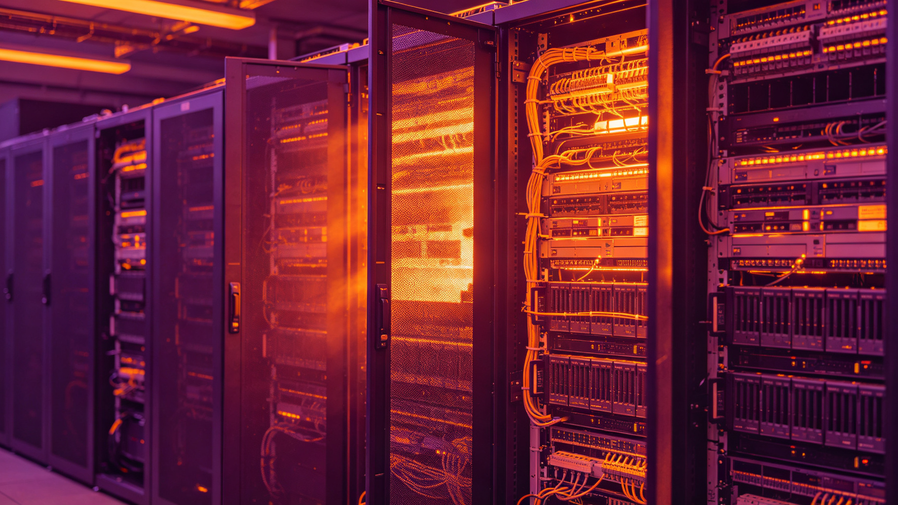
Technical guide on data center fire risk for electrical fire protection
What are the most likely ignition sources inside a data center, and where do they lurk? From overloaded power distribution units to cooling fan failures, the risk profile is more complex than many assume. A thorough fire risk analysis identifies these vulnerabilities and prioritizes mitigation measures, ensuring that protection investments target the highest-threat areas first.
Data center fire risk is dominated less by open-flame ignition sources and more by hidden electrical hazards that develop slowly inside busways, power distribution units, UPS cabinets, rack power strips, and cable bundles. Modern facilities can support 20–50 kW per rack or higher, and even small resistive faults can dissipate enough heat to degrade insulation, produce tracking currents, or ignite accumulated dust and cable jackets. A meaningful fire risk analysis therefore must identify where heat is generated, how it is contained, and how quickly suppression can reach the incipient event.
QuellPatch passive clean-agent suppression patches are designed as point-specific protection for these electrical infrastructure hazards. The product line uses microencapsulated FK-5-1-12 clean agent and passive thermal activation, allowing the patch to respond when a localized surface or air temperature reaches a calibrated threshold. This article examines electrical failure modes, a practical risk-analysis framework, patch engineering, and how passive suppression fits into a broader data center safety program.
Arcing occurs when current bridges an insulating gap, either through a loose gap, contaminated surface, or degraded insulation. Arc plasma can reach temperatures of several thousand kelvin at the fault point, even when the surrounding enclosure remains near room temperature. Such faults may be intermittent, making them difficult for conventional circuit breakers to detect before insulation ignites.
Surface tracking is a related electrical hazard on contaminated circuit boards, insulator surfaces, or damaged cable jackets. Moisture, dust, and conductive residues create small leakage currents that carbonize the surface over repeated heating cycles. The resulting carbon track can support higher currents and eventually produce an arc. In data centers, underfloor cable runs, rack PDUs, and equipment with filtered but not sealed ventilation are typical locations for tracking-related data center fire risk.
Not all electrical heating is caused by sudden faults. Mechanical connections relax under thermal cycling, busway joints can lose contact pressure, and breaker terminations may develop increased resistance. Heat generation at a connection follows the relationship P = I²R, so small resistance increases at high current produce meaningful temperature rises.
For example, a 200 A busway joint with a resistance of 50 µΩ dissipates about 2 W. If corrosion or poor torque increases that resistance to 500 µΩ, dissipation rises to 20 W. In an enclosed housing with limited airflow, that localized heat can push nearby surfaces above cable-insulation temperature limits. XLPE and PVC-insulated conductors commonly rated for 90°C or 105°C operation may begin to soften, lose mechanical strength, and contribute fuel before a full short circuit occurs.
UPS and battery rooms present a distinct electrical hazard because stored energy can drive self-heating. VRLA batteries can experience thermal runaway under overcharge or high ambient temperature, while lithium-ion battery systems can progress into thermal runaway after internal shorting, overcharge, or mechanical damage. These events may involve cell venting, flammable gas, and propagation between modules.
Passive clean-agent patches can address external ignition sources such as arcing at battery terminals, busbar connections, or control wiring, but they do not replace battery management systems, temperature monitoring, deflagration venting, or dedicated battery suppression design. The 180°C activation variant is generally relevant here because battery cabinets and nearby power electronics may have higher normal operating temperatures than general IT spaces.
A useful fire risk analysis begins with heat, not flame. For each electrical compartment, engineers should identify:
Thermographic surveys, permanently installed temperature sensors, and busway monitoring can provide baseline data. If a hotspot reaches 80–120°C, cable jackets and plastic components may begin to degrade; at 140–180°C, many electrical enclosures contain materials that can produce flammable vapors or ignite under sustained heating. Localized heat flux is more important than average room temperature because a 10–20 W fault in a sealed busway housing can create dangerous conditions while the data hall remains within normal temperature limits.
After thermal conditions are mapped, facilities can rank hazards using a failure modes and effects approach. Each item can be assessed for likelihood of failure, severity of a resulting fire, and detectability before ignition. Common high-priority locations include:
This ranking supports data center safety decisions about where to apply point-specific protection. Rather than treating all square footage equally, passive suppression can be concentrated at locations where faults are credible, hidden, and capable of developing before smoke detection or manual investigation occurs.
QuellPatch patches contain FK-5-1-12 clean agent held in microscopic polymeric shells within a flexible adhesive patch. FK-5-1-12 is electrically nonconductive, vaporizes readily after release, and leaves little or no residue on sensitive electronics. It has a short atmospheric lifetime and does not require the high storage pressure associated with pressurized cylinders.
The microencapsulation approach separates the agent into many small containers distributed across the patch surface. When the patch is heated to its activation temperature, the shell material softens or ruptures and releases agent directly near the protected surface. This is different from total-flooding clean-agent systems, which discharge large quantities through nozzles to achieve a uniform room concentration. A patch is a local device intended to suppress incipient fire growth at a specific point; it has a limited agent quantity and should not be treated as a substitute for building-level fire protection.
QuellPatch is available with activation temperatures of 80°C, 140°C, and 180°C. Selecting the correct threshold requires comparing the activation temperature with the maximum normal operating temperature of the surface and the surrounding air. The objective is to provide enough margin to avoid nuisance release while still responding before ignition becomes likely.
Passive thermal activation requires no external power, smoke detector, control panel, or manual release. This can reduce response time at the exact point where heating occurs, but it also means placement must be based on heat transfer. Patches should be located on enclosure walls, cable barriers, busway housing, or other surfaces where heat from a fault will impinge on them before or during the early stages of insulation degradation. They should not be placed on bare energized conductors unless specifically approved for that use.
Active clean-agent or sprinkler systems remain important for large or developing fires. Passive patches serve a different role: they act during the incipient period, often before a smoke detector has sampled enough combustion products to trigger an alarm. In a concealed busway or PDU, this can reduce the chance that a small resistive fault grows into a larger cable fire.
However, patches do not provide room-concentration protection, cannot address a fire outside their release area, and cannot stop a fault that releases more energy than the local agent can suppress. The design should therefore combine QuellPatch with conventional detection, circuit protection, thermal monitoring, and emergency response procedures.
QuellPatch has a 5-year service life under specified environmental conditions. Because the system is passive and non-pressurized, inspection does not require pressure gauges or cylinder weighing. A typical program includes quarterly visual checks to confirm that the patch remains adhered, is not physically damaged, has not been painted over, and shows no sign of prior activation. Facilities should also verify that the selected activation rating still matches the equipment’s operating profile after any load increase or airflow change.
Patches should be replaced at the end of the 5-year service interval, after any confirmed activation, or if inspection finds damage, lifting edges, or excessive heat exposure. Asset tags or digital maintenance records can link each patch to its location, activation rating, installation date, and replacement date.
Electrical hazards remain a central data center fire risk because high-current distribution systems can develop localized heating long before a visible fire appears. A structured fire risk analysis should map normal and fault temperatures, rank ignition sources by likelihood and consequence, and place protection where heat is most likely to concentrate. QuellPatch passive clean-agent patches provide one layer of that protection by using microencapsulated FK-5-1-12 and passive thermal activation at 80°C, 140°C, or 180°C, depending on the equipment environment.
When selected with appropriate temperature margins and maintained through their 5-year service life, these patches can help suppress incipient electrical events near busways, PDUs, UPS systems, and cable infrastructure. They are most effective when integrated with active suppression, electrical maintenance, thermographic inspection, and formal data center safety procedures rather than treated as a standalone solution.
A: Many data center fire losses originate in electrical infrastructure rather than in servers themselves, including UPS systems, switchgear, PDUs, busways, transformers, battery cabinets, and cable compartments. Failures often begin with overheating connections, arcing, insulation degradation, or component faults that develop inside enclosures before smoke or flame reaches room detection. That is why risk analysis should look at both white-floor spaces and concealed electrical compartments.
A: A practical assessment identifies ignition sources, fuel sources, criticality of each zone, detection timing, suppression coverage, and failure consequences such as downtime, smoke damage, and business interruption. Engineers should inspect UPS and PDU terminations, cable bundles, busway connections, battery systems, generator controls, and hot-aisle conditions, then compare safeguards with NFPA 75, NFPA 76, NFPA 2001, and site reliability requirements. The output should prioritize high-energy, high-consequence enclosures where hidden incipient fires can grow quickly.
A: Base the choice on the highest normal surface or air temperature at the mounting location, plus a safety margin to prevent nuisance activation. Use 80°C for cooler cable compartments, general control cabinets, and areas below about 60°C; use 140°C for hotter PDUs, busway connections, generator compartments, or similar equipment; use 180°C only where measured operating temperatures justify the higher rating. Record temperatures under peak load before selecting the variant.
A: Installation should be performed by qualified personnel following the manufacturer’s instructions, NFPA 70E or equivalent electrical-safety rules, arc-flash PPE requirements, and site lockout/tagout procedures. Patches are typically applied to dry, non-current-carrying metal surfaces inside enclosures and do not require wiring or power. Whether energized installation is permitted depends on the equipment rating, access, clearance, and facility safety policy.
A: No. QuellPatch is a point-of-origin, passive suppression layer intended to address incipient fires inside specific electrical enclosures, not a replacement for building sprinklers, room-level clean-agent systems, VESDA, smoke detection, or alarm monitoring. It complements those systems by releasing FK-5-1-12 directly at a heated component when its rated temperature is reached. Data centers should still maintain a layered protection strategy aligned with NFPA 75, NFPA 76, and NFPA 2001 where applicable.
FIREQUELL QuellPatch delivers automatic, maintenance-free clean-agent protection for electrical panels, battery cabinets and control rooms — designed to meet FM Approved, UL Listed, CE and UKCA requirements.
Request a Site Assessment