2026-08-11 ·
FIREQUELL Engineering Team
How do Cell-Level vs Pack-Level Lithium Containment compare for fire-protection applications?
When a lithium cell enters thermal runaway, it releases flammable electrolyte vapor and can reach temperatures above 600°C in seconds. The containment strategy you choose—cell-level or pack-level—determines how much of that energy is absorbed before neighboring cells ignite. Engineers must weigh response time, agent volume, and serviceability when deciding which approach fits their risk profile.
8. Standards, Sizing, and Installation Validation
Selecting between cell-level and pack-level containment should be tied to the battery architecture, abuse likelihood, and the acceptance criteria used in validation. For QuellPatch FK-5-1-12 systems, the starting point is the cell format and expected thermal-runaway behavior: cylindrical cells commonly vent through a dedicated top or bottom vent, prismatic cells may release gas along seams or relief plates, and pouch cells can swell and rupture over a larger area. Cell-level patches are most effective when sized to cover the expected vent path and adjacent heat-transfer surface, typically allowing 15–25% overlap beyond the measured vent or hot-face zone. Pack-level panels or blankets, by contrast, should cover the entire high-risk envelope, including busbar runs, interconnect boards, and adjacent module faces, rather than only the visible cell caps.
Performance claims should be evaluated against recognized lithium-ion fire and thermal-runaway standards rather than generic fire-test reports. NFPA 855 provides the overall framework for stationary energy storage system fire safety, while UL 9540A evaluates thermal runaway propagation at cell, module, unit, and installation levels. IEC 62619 and IEC 63056 address safety requirements for industrial and stationary secondary lithium cells and batteries, and UL 723 or ASTM E84 may be relevant for surface-burning characteristics of materials used in occupied spaces. In practice, a compliant design does not simply contain an open flame; it should demonstrate reduced surface temperatures, delayed or prevented propagation, controlled venting, and limited ejection of molten or burning debris under the selected test protocol.
Temperature targets are especially important when validating installation geometry. During a propagating event, local cell-can or vent gas temperatures can exceed 600°C, and adjacent cells may reach thermal-runaway onset between 130°C and 200°C depending chemistry and state of charge. A well-installed QuellPatch layout should maintain neighboring cell surfaces below the propagation threshold for the duration defined in the project test or risk assessment, while pack-level barriers should reduce exposed enclosure surfaces to a level compatible with adjacent equipment and building construction. Because FK-5-1-12 is stored and released locally in a passive assembly, no piping network, pressure switch, or control panel is required, but surface preparation, compression, edge sealing, and clearance from moving service parts must still follow the approved drawing.
Installation validation should therefore include both dimensional inspection and traceability. Confirm that every specified cell or module location receives the correct patch part number, that adhesive or mechanical attachment is continuous across the intended contact area, and that vents are not obstructed in a way that causes unintended pressurization. For pack-level systems, verify that barriers do not block required service disconnects, BMS sensors, or pressure-relief paths. The final record should capture cell chemistry, capacity, arrangement, patch coverage area, test standard, and observed maximum temperatures. This documentation makes the cell-level versus pack-level decision auditable and gives integrators, authorities having jurisdiction, and end users a defensible basis for accepting the passive protection design.
Frequently Asked Questions
Q: How long until cell-level suppression becomes a code requirement?
A: It is not in NFPA 855 or UL 9540A as of writing, but several insurers offer premium credit for cell-level coverage. Expect code-level adoption by 2027–2028.
Q: Does cell-level suppression void the cell warranty?
A: It depends on the cell manufacturer; some explicitly exclude warranty if any non-OEM material is mounted on or near the cell can. Check the cell datasheet; many passive patches are cell-neutral when mounted on the busbar side rather than the can.
Q: Can a 21700 cell discharge flame be suppressed inside the cell itself?
A: Yes. The thermal window between venting and propagation is ~5–10 s. A patch mounted on the cell vent face ruptures in <1 s and discharges enough agent to keep the vent gas below ignition energy.
When Each Strategy Wins
Overview
Lithium-ion containment strategy is the most consequential engineering decision in any BESS, EV charging cabinet, or stationary storage installation. Two distinct approaches dominate: cell-level suppression built into the module itself, and pack-level suppression at the enclosure exterior. The decision is driven by hazard class, recovery objectives, and total installed cost. A practical framework resolves most cases.
1. Two Distinct Failure Modes
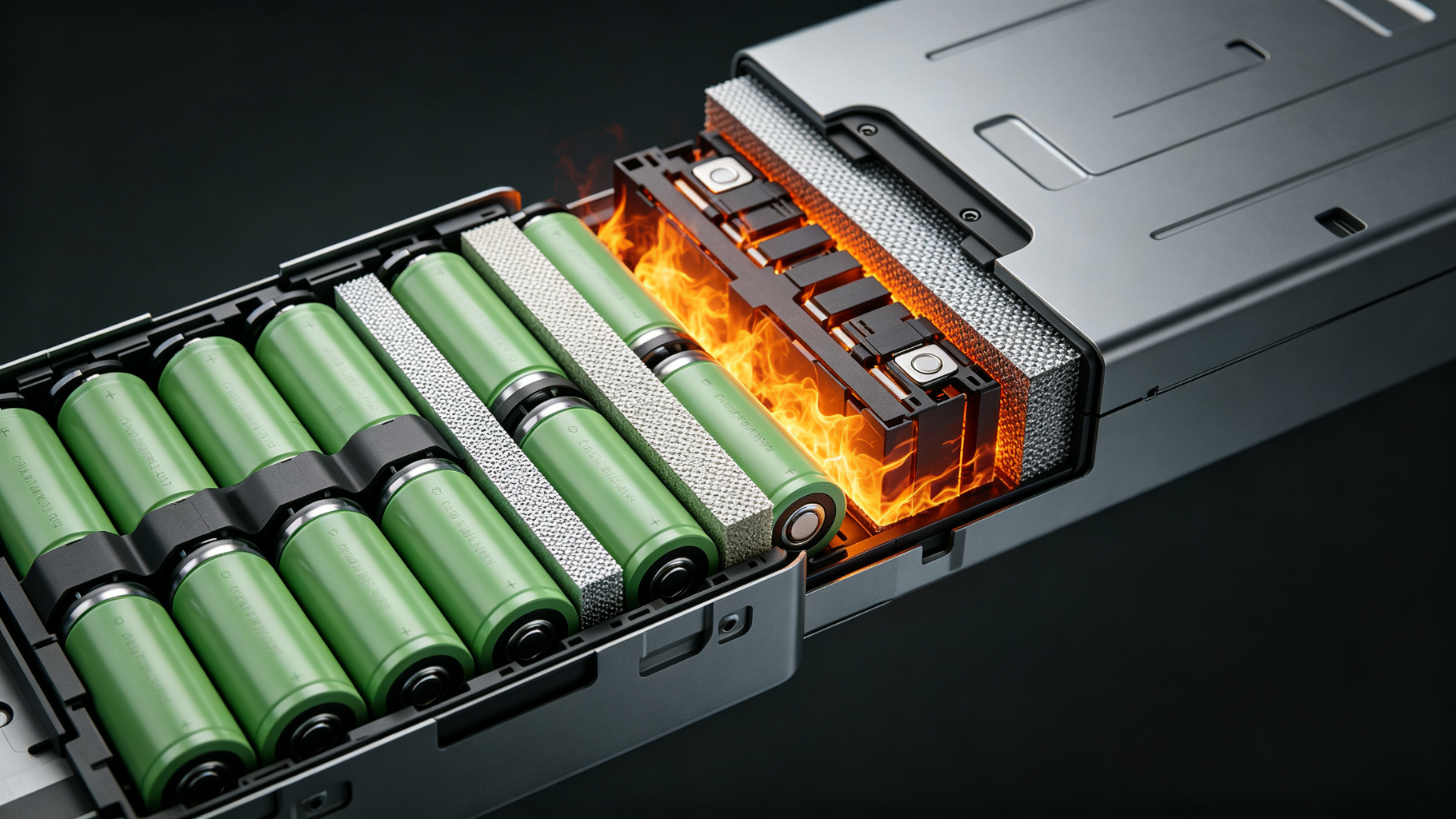
Lithium-ion cells fail in two ways. Thermal runaway begins at the cell—a chain reaction inside the jellyroll—and vents through the cell casing. Propagation is the spread of that vented thermal energy to neighboring cells. Cell-level suppression contains the runaway event at its source; pack-level suppression contains the propagation, but not the runaway itself.
2. Cell-Level Suppression: When to Use
Cell-level suppression is the right choice when (a) the cell format allows for internal mounting (cylindrical 18650/21700 large format cells), (b) the enclosure is small enough that the cell-to-cell spacing allows direct agent access, and (c) the recovery objective is to save at least some of the cells. Typical applications: EV battery modules, small BESS racks, military portable power.
3. Pack-Level Suppression: When to Use
Pack-level suppression is the right choice when (a) cell format is pouch or prismatic (cell-level mounting is impractical), (b) the enclosure is large (rack-scale or container-scale), or (c) the recovery objective is asset protection rather than cell preservation. Typical applications: utility BESS containers, EV charging cabinets, UPS battery rooms.
4. A Decision Matrix
Use the matrix below to translate the most common design inputs into a strategy recommendation.
- Cell format: cylindrical / 18650 / 21700: Cell-level optional
- Cell format: pouch / prismatic: Pack-level preferred
- Module volume < 30 L: Cell-level viable
- Module volume 30–200 L: Pack-level recommended
- Recovery objective: cell preservation: Cell-level
- Recovery objective: container preservation: Pack-level
5. The Combined Strategy
The strongest installations use both. Cell-level suppression (typically a thermally-triggered FK-5-1-12 patch between every Nth cell) catches the runaway early; pack-level suppression (typically a clean-agent cylinder or a passive panel around the enclosure exterior) catches the propagation if a cell-level event escapes. The combined cost is modest relative to the equipment it protects.
6. Practical Specifications
For a typical 100 kWh BESS rack, specify:
• 4 cell-level patches per module (1 in every 8 cells across the diagonal)
• 1 pack-level patch inside each rack enclosure
• 1 pack-level clean-agent cylinder for the container-level propagation
• A thermal indicator on every cell-level patch for diagnostics
A complete specification is rarely more than 2–3% of the rack capital cost.
7. Why a Passive Design Helps
Active suppression introduces wiring, detectors, and a power source—all of which can themselves be ignition sources inside a battery enclosure. Passive suppression eliminates these failure modes. The cell-level patch discharges at the runaway cell without any signal from a controller; the propagation is stopped before the active system could even trigger.
Related Reading