
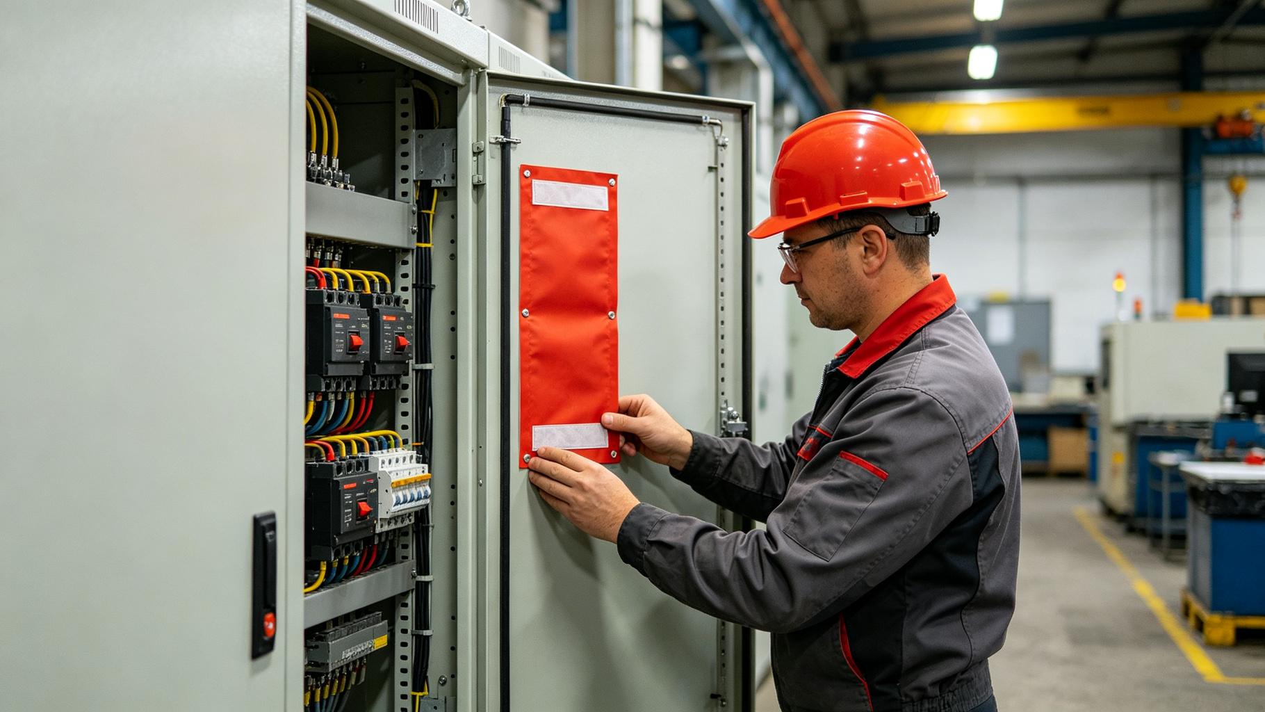
Published: July 2026 • Installation Technical Guide
What is Installation & Positioning Guide?
Installing passive fire suppression in low-voltage switchgear and distribution boards demands precision—a misaligned patch can mean the difference between containing a fire and losing an entire panel. This guide covers the critical steps: measuring enclosure volume, placing devices near heat sources, and securing them without obstructing airflow. Whether you're retrofitting an existing board or designing a new one, these best practices ensure reliable activation when it matters most.
1. Why Positioning Matters
Passive fire suppression patches are thermally activated point-protection devices. Unlike total-flooding systems that are engineered to achieve uniform agent concentration throughout an entire enclosure, passive patches release agent locally and rely on natural dispersion within the enclosed space. Proper positioning is therefore critical to performance — a correctly selected patch installed in the wrong location may not activate early enough or may not achieve effective concentration at the fire location.
This guide provides practical recommendations for positioning FIREQUELL devices in common low-voltage electrical equipment: distribution boards, switchgear, motor control centers, and panelboards.
2. General Principles
2.1 Proximity to Likely Ignition Sources
Patches should be positioned as close as practical to the most probable fire initiation points within the enclosure. In LV electrical equipment, these are typically:
- Busbar connections and joints: Loose or corroded connections at busbar taps are a leading cause of electrical fires
- Circuit breaker terminations: Both line and load side connections, particularly on high-current feeders
- Contactor and relay contacts: Pitting and wear from switching can lead to arcing and overheating
- Terminal blocks: Loose set screws, stripped threads, and undersized terminations
- Power electronic components: VFDs, soft starters, and UPS modules that generate significant heat
- Neutral and ground connections: Often overlooked but subject to overheating from harmonic currents
2.2 Heat Activation Considerations
Patches activate when the patch surface reaches its rated temperature. Key factors:
- Line of sight to heat source: The patch must be in the thermal radiation field of the developing fire. Positions behind metal barriers or in dead air pockets may experience delayed activation.
- Mounting surface: Mounting on metal surfaces (which conduct heat away) may slightly delay activation compared to mounting on plastic or in free air. This is generally acceptable and should not be compensated by selecting a lower temperature grade.
- Stratification: Hot gases rise. Patches mounted in the upper portion of an enclosure will generally activate earlier than those at the bottom for fires below. However, agent dispersion from a high mounting point may be less effective for fires at the bottom.
- Ambient temperature: Select the temperature grade based on maximum normal operating temperature at the mounting location, not general room temperature. The interior of a loaded switchboard in a 40°C ambient can reach 60-70°C under normal conditions.
2.3 Agent Dispersion Geometry
Upon activation, FK-5-1-12 vaporizes and disperses through the enclosure volume. Consider:
- Unobstructed dispersion: Patches should not be placed inside sealed wireways or behind solid barriers that would prevent agent circulation.
- Central positioning: For single-patch installations, mounting near the geometric center of the enclosure volume provides the most uniform agent distribution.
- Multiple compartments: Each separately enclosed compartment (e.g., individual breaker cubicles in MCCs) should have its own patch. Agent does not effectively travel through small openings or around substantial barriers.
- Top vs. side mounting: FK-5-1-12 vapor is significantly heavier than air (vapor density ~11 times air). It will tend to sink after release. Top-mounted patches provide good downward coverage; bottom-mounted patches may not effectively protect upper areas.
3. Equipment-Specific Recommendations
3.1 Distribution Boards / Panelboards (100-800A)
Typical enclosure: Wall-mounted NEMA 1/3R or IP4x enclosures, 200-800mm wide, 600-1200mm tall, 150-250mm deep.
Recommended configuration:
- One QPF-0110-STM (Standard 100×100mm) for enclosures up to approximately 0.1m³ internal volume
- Position: Centered on the interior of the door or on the interior back panel near the main breaker location, at approximately 2/3 height
- For larger panelboards (800A+), consider two patches: one near main breaker, one near the busbar midpoint
- Temperature grade: M-grade (140°C) for most indoor installations; L-grade (80°C) only if ambient is consistently below 40°C and the panel contains sensitive electronics
3.2 Low-Voltage Switchgear (800-4000A)
Typical enclosure: Floor-standing, metal-enclosed, multiple vertical sections, each 600-1000mm wide × 2000-2200mm tall × 800-1500mm deep.
Recommended configuration:
- Minimum one patch per vertical section/cubicle
- Breaker cubicles: QPF-0110-STM or QPA-0110-STM (QuellArmor) mounted on the cubicle door or side wall, upper third of the cubicle
- Busbar compartments: QPF-0210-STM (Large 200×100mm) mounted at the top of the busbar compartment, centered over the bus run
- Cable compartments: One patch per cable compartment, positioned near the cable termination area
- For critical switchgear (main-tie-main configurations, hospital/data center applications), use QuellArmor with thermal indicator for pre-fire warning
3.3 Motor Control Centers (MCCs)
Typical enclosure: Multi-section, with individual bucket units ranging from 300mm to 900mm tall.
Recommended configuration:
- Each starter bucket > 100A rated: one QPF-0105-STM (Slim 100×50mm) inside the bucket, mounted on the bucket door or side plate
- Small buckets (< 50A): Can be protected by a single patch in the horizontal wireway or common compartment
- Main horizontal bus compartment: QPF-0210-STM per section
- Vertical wireways: One patch per vertical section, mid-height
- Consider QPA-0110-STM (QuellArmor) for high-value or critical motor starters
3.4 Variable Frequency Drives and Power Electronics
Special considerations: VFDs and similar equipment contain DC bus capacitors that can store significant energy and produce intense fires. Internal ambient temperatures are typically higher than standard switchgear.
- Use H-grade (180°C) patches to avoid nuisance activation from normal operating temperatures
- Position near the DC bus capacitor bank and IGBT modules — the highest-risk components
- For drives > 50kW, use QPF-0210-HCH (High-Capacity) or QPA-0210-HCH
- Ensure the patch does not obstruct ventilation airflow or contact heatsinks
4. Sizing and Coverage Guidelines
The following table provides general guidance for enclosure volume coverage. These are starting points for typical electrical enclosures; actual requirements vary based on enclosure geometry, fire load, ventilation, and risk assessment.
| Product | Dimensions | Typical Coverage* | Typical Application |
|---|---|---|---|
| QPT-0060 | 60×60mm | ~0.02 m³ | Small consumer devices, individual outlets |
| QPF-0083 | 80×30mm | ~0.03 m³ | Small junction boxes, compact enclosures |
| QPF-0105 | 100×50mm | ~0.06 m³ | MCC buckets, small panels |
| QPF-0110 | 100×100mm | ~0.12 m³ | Standard distribution panels (most common) |
| QPF-0210 | 200×100mm | ~0.25 m³ | Large panels, switchgear cubicles |
| QPA-0210-HCH | 200×100mm (HC) | ~0.5 m³ | BESS cabinets, large switchgear, drives |
*Coverage figures are approximate guidelines for typical enclosed electrical equipment with normal fire loading. Not a substitute for engineering assessment.
5. Mounting Methods
5.1 Adhesive Mounting (Standard)
All FIREQUELL patches come with high-performance acrylic adhesive backing suitable for metal and most plastic surfaces.
- Surface must be clean, dry, and free of grease, oil, and loose paint
- Wipe with isopropyl alcohol and allow to dry before application
- Apply firm pressure across the entire patch surface for 30 seconds
- Service temperature range of adhesive: -40°C to +150°C
- For high-vibration environments, consider additional mechanical retention
5.2 Magnetic Mounting (QuellArmor -MAG option)
QuellArmor variants with magnetic mounting are available for temporary installations, retrofit applications, or where adhesive is not desirable.
- Rare-earth magnets provide secure attachment to steel surfaces
- Not suitable for aluminum, stainless steel (non-magnetic), or plastic enclosures
- Allows repositioning and removal for inspection
- Verify magnetic hold on painted or coated surfaces — thick paint reduces holding force
5.3 Snap/DIN Rail Mounting (QuellArmor -SNAP option)
For installations requiring mechanical retention or DIN rail compatibility.
- Clips directly to standard 35mm DIN rail
- Suitable for high-vibration industrial environments
- Allows easy replacement after activation
6. Installation Best Practices Checklist
- De-energize equipment before installation where possible. Follow all lockout/tagout procedures and electrical safety requirements (NFPA 70E, CSA Z462, or local equivalent).
- Select the correct temperature grade based on measured or specified maximum normal operating temperature at the mounting location.
- Clean the mounting surface thoroughly with isopropyl alcohol; allow to dry completely.
- Position the patch with the agent-release side facing into the enclosure volume (not pressed against a solid surface).
- Do not cover the patch with insulation, wire bundles, or other materials that would insulate it from heat or block agent release.
- Maintain clearance from live parts per applicable electrical codes. The patch is non-conductive but should not be installed in positions where it could contact energized buswork during normal operation or fault conditions.
- Record installation — note location, SKU, installation date, and expected replacement date (5 years from installation) in your maintenance system.
- Verify thermal indicator (QuellArmor) is in unactivated state after installation.
- Do not paint over the patch or apply any coating.
- For multiple patches in a single enclosure, space them to provide overlapping coverage rather than concentrating them in one area.
7. Maintenance and Inspection
FIREQUELL passive devices require no operational maintenance. However, the following are recommended during normal routine maintenance of the electrical equipment:
- Visual inspection annually: Verify the patch is still securely mounted, has not been damaged, and (for QuellArmor) the thermal indicator has not activated.
- Replacement after 5 years: Replace all patches at the 5-year mark from installation date. The agent and materials are rated for 5-year service life.
- Replacement after activation: If a patch has discharged (evidenced by ruptured envelope and absence of liquid agent), replace immediately and investigate the cause of the thermal event.
- Replacement after indicator activation: If the thermal indicator has changed color but the patch has not discharged, investigate the overheating cause and consider replacing the indicator patch.
8. Conclusion
Proper positioning is the single most important installation factor affecting the performance of passive fire suppression patches. By following the principles of proximity to ignition sources, consideration of thermal activation dynamics, and attention to agent dispersion geometry, installers can ensure that FIREQUELL devices provide effective, reliable protection. When in doubt about specific applications — particularly large, complex, or high-risk installations — consult FIREQUELL engineering for application-specific guidance. The goal is not to replace engineered fire suppression systems where they are required, but to provide an effective, reliable, zero-maintenance first line of defense at the exact locations where electrical fires most commonly originate.
Disclaimer: This guide provides general recommendations for typical installations and does not constitute engineering design for specific projects. All electrical work must be performed by qualified personnel in accordance with applicable codes and standards. FIREQUELL does not accept liability for installations performed contrary to these guidelines or without proper engineering assessment of specific conditions.
Frequently Asked Questions
Q: Can the patch be installed on a hot busbar?
A: Yes. Surface preparation requires power-off isolation only for the busbar cover; the patch itself is applied with acrylic adhesive and needs no live work.
Q: What is the recommended spacing on a panel?
A: One patch per 0.25 to 0.5 cubic metres of internal cabinet volume, mounted within 100 mm of the highest-risk components.
Q: How is the patch verified post-install?
A: Visual inspection of the thermal indicator label and the FM/UL mark on the housing; recorded in the asset register.